A correctly sized valve can still perform poorly when it is installed against its intended flow direction or in an orientation that prevents reliable operation. Direction concerns the way fluid passes through the valve. Orientation concerns the physical position of the body, stem, actuator, hinge, disc, or internal closure relative to the pipe and gravity. Both must be confirmed before installation.
The safest rule is to follow the approved valve drawing, body markings, manufacturer instructions, piping specification, and project engineering documents. The guidance below explains the engineering logic behind those instructions and helps buyers identify the questions that should be resolved before shipment or site installation.
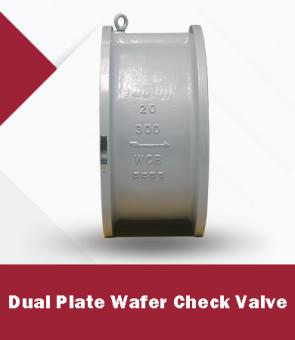
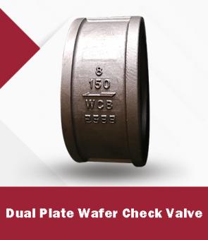
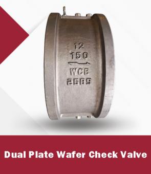
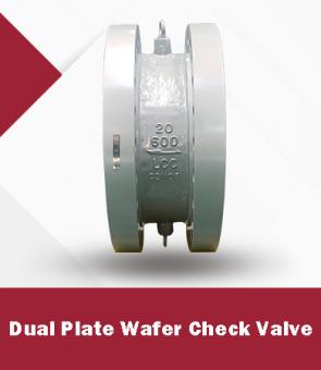
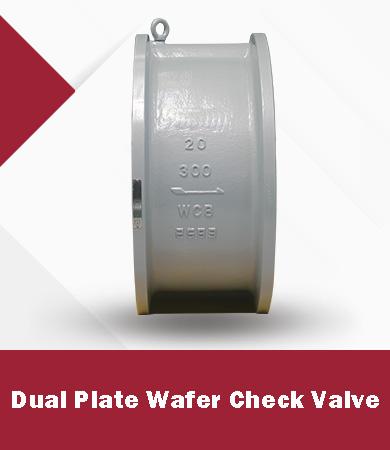
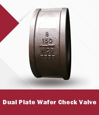
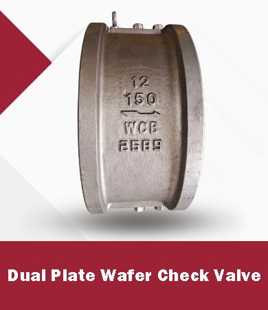
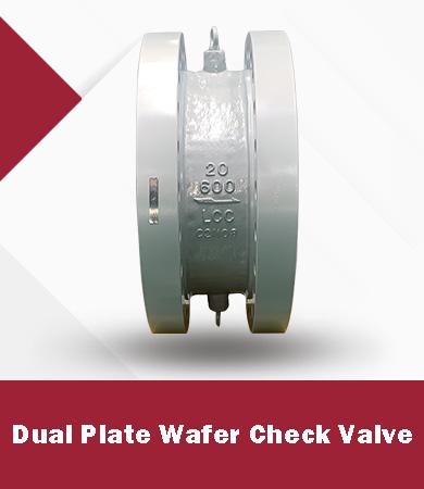
Many unidirectional valves carry a cast, stamped, or tagged arrow. That arrow indicates the intended process flow through the pressure boundary; it should not be confused with an actuator opening arrow or a handwheel rotation marking. If markings conflict with the drawing or datasheet, quarantine the item and obtain written clarification rather than guessing.
· Match the valve tag and serial number to the approved datasheet and drawing.
· Confirm the body arrow, inlet and outlet ends, and any preferred-pressure side.
· Check whether the valve is unidirectional, bidirectional, or bidirectional only under stated differential-pressure limits.
· Verify the required stem, shaft, hinge-pin, and actuator position.
· Confirm access for operation, packing adjustment, bolting, drainage, and removal.
|
Valve type |
Direction concern |
Orientation concern |
What to confirm |
|
Gate valve |
Many standard designs can isolate in either direction, but pressure-relief cavities, bypasses, seats, and special trim can make direction important. |
Stem and actuator access; drainage and trapped-cavity risk; manufacturer limits for non-vertical mounting. |
Seat design, preferred pressure side, cavity relief, bypass arrangement, stem position. |
|
Globe valve |
Flow path and pressure side affect pressure drop, operating force, seat loading, and shutoff behavior. |
Stem is commonly installed upright where practical; alternate positions require design confirmation. |
Body arrow, flow-to-open or flow-to-close intent, actuator thrust, service conditions. |
|
Must allow forward flow to open the disc and reverse flow to close it. |
Hinge axis and gravity must support disc travel; vertical use depends on flow direction and qualified design. |
Arrow, hinge-pin position, horizontal/vertical approval, minimum flow behavior. |
|
|
Lift or piston check valve |
Forward flow lifts the closure; reverse pressure returns it to the seat. |
Gravity-assisted designs normally require a specific body orientation unless spring loading permits alternatives. |
Arrow, spring option, approved mounting positions, cracking pressure. |
|
Ball valve |
Many floating-ball designs are bidirectional, but vented balls, cavity relief, single-piston seats, drains, and special trims can establish a preferred direction. |
Stem and actuator accessibility; cavity drain/vent location; support for heavy actuators. |
Seat arrangement, vent-hole direction, relief side, bore orientation, actuator support. |
|
Butterfly valve |
Some resilient designs are bidirectional; high-performance and triple-offset designs may have a preferred pressure direction. |
Shaft orientation, disc clearance, actuator access, and solids or sediment behavior matter. |
Preferred pressure side, shaft position, disc-to-pipe clearance, gasket compatibility. |
In a globe valve, the fluid turns through the body and passes the seat. Depending on the design, the manufacturer may specify flow under the disc or over the disc. That choice can change the force required to operate the valve, the loading on the stem and packing, the stability of throttling, and the way the valve fails or seals under differential pressure. There is no universal direction that is correct for every globe valve and service.
For high differential pressure, steam, flashing service, severe throttling, or actuated operation, the selected direction should be reviewed with the manufacturer using actual upstream and downstream conditions. Actuator sizing must use the specified direction and worst credible differential pressure.
A check valve depends on differential pressure and the movement of a disc, piston, ball, or plates. Gravity, spring force, hinge geometry, installation angle, and flow velocity all influence opening and closing. Installing a gravity-dependent check valve in an unapproved orientation can cause delayed closure, chatter, reverse flow, or failure to open fully.
A check valve should not be selected from line size alone. Confirm the expected flow range, fluid density and viscosity, installation position, nearby elbows or pumps, transient risk, allowable pressure drop, and required cracking pressure. The selected valve should operate stably at normal and reduced flow, not merely fit between the flanges.
· Reversing an unidirectional valve because the body arrow was hidden by insulation or paint.
· Mounting a swing or lift check valve in a position not approved by the manufacturer.
· Placing a heavy actuator sideways without adequate stem, bracket, or piping support.
· Allowing a butterfly-valve disc to contact pipe bore, lining, flange gasket, or adjacent fittings.
· Installing too close to a pump, elbow, reducer, or control element where disturbed flow promotes check-valve chatter.
· Leaving insufficient clearance for handwheel travel, actuator removal, packing service, or bonnet disassembly.
· Failing to flush debris before commissioning, leading to seat damage or blocked internal movement.
1. Verify tag, size, class, material, trim, end connection, and approved drawing.
2. Identify process flow and compare it with the valve body arrow and piping isometric.
3. Confirm all approved mounting positions and any limits on stem or shaft angle.
4. Inspect the bore and closure for transport restraints, debris, corrosion protection, and damage.
5. Check flange alignment, gasket location, weld-end preparation, pipe cleanliness, and support loads.
6. Support actuators and gearboxes where required; do not use the valve to correct piping misalignment.
7. Stroke the valve and verify position indication before pressurization.
8. Commission gradually while monitoring leakage, vibration, abnormal torque, noise, and check-valve stability.
Provide valve type, size, pressure class, material, medium, design and operating pressure/temperature, normal and minimum flow, upstream and downstream pressure, installation orientation, flow direction, end connection, actuator or gearbox, piping layout constraints, applicable standards, inspection scope, and required documents. For check valves, add cracking pressure, allowable pressure drop, transient concerns, and distance from pumps or elbows when known.
Can every gate valve be installed in either flow direction?
No. Many conventional designs provide bidirectional isolation, but seat construction, cavity relief, bypasses, pressure-equalizing features, and special service designs can impose a preferred direction.
Can a globe valve be installed opposite the arrow?
Do not reverse it without written design confirmation. Direction affects operating force, pressure loading, throttling behavior, and shutoff performance.
Can a swing check valve be installed vertically?
Only when the specific design and flow direction are approved for vertical installation. The disc must open and close reliably under the expected flow and gravity conditions.
Does a bidirectional ball valve have no preferred side?
Not always. Vented cavities, relief features, drain orientation, seat design, or special trim can create a preferred pressure or flow side.
What if the body arrow conflicts with the piping drawing?
Stop installation, identify the exact valve, and obtain written clarification from engineering and the manufacturer before proceeding.
Tel: 86-0592-5185-378
Whatsapp :+86 199 9681 0137
Email : sales@dawalvalve.com



Friendly Links :

 Tel : 86-0592-5185-378
 Email : sales@dawalvalve.com