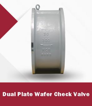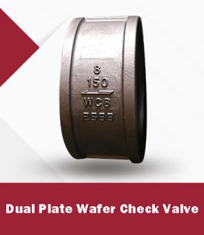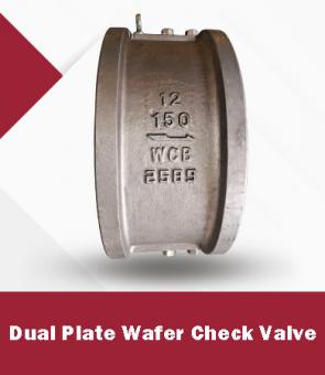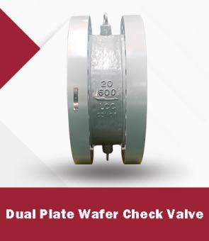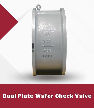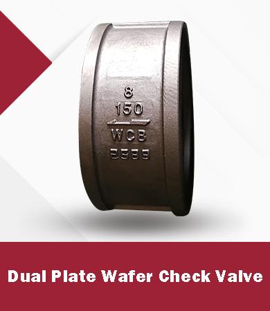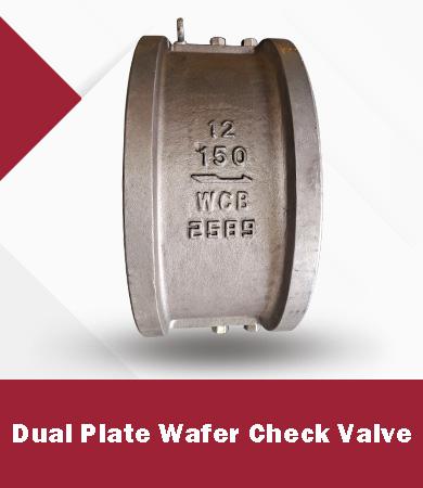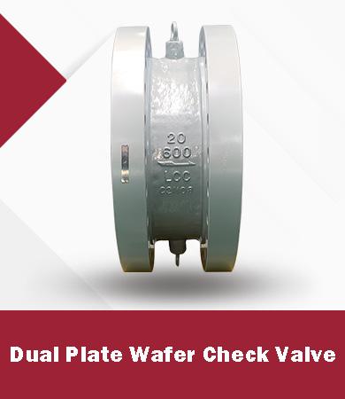
Dual plate wafer check valves and axial flow check valves both prevent reverse flow, but they solve different piping problems. A dual plate wafer design is compact, relatively light, and economical across many water, utility, and process services. An axial flow design uses a streamlined flow path and spring assisted axial closure to reduce pressure loss and limit reverse velocity before shutoff. It is often considered for high flow, high pressure, compressor, pump discharge, and surge sensitive pipelines.
The correct choice depends on more than nominal size and pressure class. Engineers should compare the actual flow range, available differential pressure, required closure response, line velocity, installation orientation, solids content, maintenance access, and the consequence of water hammer or compressor surge. This guide provides a practical basis for preparing a technically complete inquiry.
A dual plate wafer check valve contains two semicircular plates mounted on a central hinge pin. Forward flow opens the plates against one or more torsion springs. When flow decelerates, the springs start closing the plates before substantial reverse flow develops. The short face to face dimension fits between mating flanges and reduces valve weight compared with many full body swing check valves.
The design is available in wafer, lug, and double flanged configurations. Selection details include internal or external hinge pin arrangement, retainerless body construction, spring material, seat material, body material, flange compatibility, and the intended installation orientation.
An axial flow check valve guides a disc along the pipe axis. Forward pressure moves the disc away from the seat against a spring, while a shaped body and diffuser create a streamlined passage. As forward flow falls, the spring drives the disc toward the seat. The short disc stroke and axial motion can produce fast, controlled closure with low slam risk when the spring and trim are matched to the system dynamics.
The body is normally longer and heavier than a wafer valve, but the internal flow path can provide lower pressure loss at high flow rates. Axial designs are commonly evaluated for transmission pipelines, high pressure pump discharge, compressor discharge, and services where energy loss or transient control justifies a higher purchase cost.
|
Selection factor |
Dual plate wafer check valve |
Axial flow check valve |
|
Installation envelope |
Very short face to face and low weight |
Longer body and higher installed weight |
|
Pressure loss |
Low to moderate when correctly sized |
Often lower at high flow because of streamlined passage |
|
Closure behavior |
Spring assisted plates shorten travel and reduce reverse flow |
Spring assisted axial disc provides short stroke and controlled closure |
|
Water hammer control |
Good when velocity and spring selection are appropriate |
Strong option for surge sensitive high energy systems |
|
Typical cost |
Usually lower initial cost |
Usually higher initial cost |
|
Large size practicality |
Compact design is attractive in large diameters |
Available in large sizes but body weight and cost rise |
|
Dirty or solids bearing fluid |
Hinge and spring areas require service review |
Close clearances and guided disc require service review |
|
Maintenance access |
Valve must often be removed from between flanges |
Body design may allow more controlled internal access depending on model |
A dual plate wafer check valve is often the practical starting point for cooling water, fire water, seawater, and general utility lines where space and weight matter. Confirm that the selected body, plate, shaft, spring, and seat materials suit the water chemistry and temperature. For seawater or corrosive water, do not specify only the body material; trim and spring materials can control service life.
Both designs can serve pump discharge lines. The decision should consider pump trip behavior, fluid column length, elevation change, line velocity, and the time at which reverse flow begins. A dual plate valve can provide compact spring assisted closure for many centrifugal pump systems. An axial flow valve becomes more attractive when the hydraulic transient is severe, the pump operates at high energy, or lifecycle energy loss is important.
Axial flow check valves are frequently evaluated for gas transmission and compressor discharge because the axial disc can respond quickly and the streamlined passage limits pressure loss. The supplier should check minimum flow, gas density, pressure, temperature, and compressor operating cases. A valve that is stable at design flow may chatter at recycle or turndown conditions if the available flow does not hold the disc in a stable position.
At high pressure and high velocity, the cost of pressure loss and the consequence of slam both increase. Compare the manufacturer's flow coefficient, predicted pressure drop, dynamic closure data, body pressure class, end connection, and applicable design standard. An axial design may be justified, but a correctly sized dual plate valve can remain suitable when the transient risk and energy penalty are acceptable.
Do not compare valves using nominal size alone. Request a flow coefficient or pressure loss curve for the exact size, class, and internal design. Calculate pressure drop at minimum, normal, and maximum flow. A lower purchase price can be offset by years of pumping or compression energy, while a small pressure loss difference may not justify a more expensive valve in intermittent service.
The installed comparison should use the same fluid properties and flow cases. Reducers, nearby elbows, and disturbed inlet flow can affect performance. If the valve will operate far below its design flow for long periods, confirm disc stability rather than relying only on the maximum flow pressure drop.
Check valve slam occurs when reverse flow accelerates before the closure member reaches the seat. The sudden stop of that reverse flow creates a pressure wave. A fast closing label by itself does not prove that a valve will prevent surge. Closure depends on the moving mass, travel distance, spring force, flow deceleration rate, orientation, and the hydraulic system.
For critical pump stations or long pipelines, provide the valve manufacturer with transient data or request dynamic performance information suitable for a surge study. Spring selection should be treated as an engineered parameter. A spring that is too weak may allow excessive reverse velocity; a spring that is too strong can increase opening pressure, pressure loss, or low flow instability.
An oversized check valve may not open fully at normal flow. Plates or discs can hover, chatter, or strike their stops, which accelerates wear and increases noise. Ask the supplier for minimum stable flow or velocity guidance for the proposed valve and orientation. If the operating range is wide, evaluate each case rather than sizing only for the line's maximum design flow.
For dual plate valves, review plate opening angle and spring behavior. For axial flow valves, review disc lift and spring compression across the operating range. In both cases, the best nominal size may be smaller than the pipeline, provided reducer effects, velocity, pressure loss, and maintenance requirements are acceptable.
· Confirm the permitted horizontal and vertical flow directions for the exact valve design.
· Provide enough straight pipe where the manufacturer requires stable inlet flow.
· Check that flange inside diameter and gasket position do not obstruct plate movement.
· Verify that mating flanges, bolting, and face finish match the selected wafer, lug, or flanged body.
· Allow lifting and removal space based on the actual valve weight and maintenance method.
· Mark the flow arrow clearly and protect internal parts from debris during installation and flushing.
|
Service condition |
Items to verify |
|
Carbon steel process service |
Body grade, corrosion allowance, trim hardness, seat leakage requirement |
|
Low temperature service |
Body and trim impact properties, spring material, seat temperature capability |
|
Seawater or corrosive water |
Body coating or alloy, plate and shaft alloy, spring corrosion resistance, galvanic compatibility |
|
Sour service |
NACE material compliance, hardness limits, bolting and trim certification |
|
High temperature service |
Metal seat design, spring relaxation resistance, thermal expansion and leakage expectation |
|
Abrasive or solids bearing fluid |
Flow path, hinge or guide wear, hardfacing, flushing and inspection access |
· Specifying only size and pressure class without minimum normal and maximum flow
· Assuming every non slam check valve has the same dynamic closure performance
· Choosing line size without checking minimum stable velocity
· Comparing pressure loss data from different flow rates or fluid properties
· Ignoring plate spring shaft guide and seat materials
· Failing to state installation orientation and vertical flow direction
· Using a generic API 594 reference without confirming the required valve category and face to face dimensions
· Omitting surge requirements inspection scope coating and documentation from the purchase specification
1. Define fluid properties and minimum normal and maximum operating cases.
2. Identify whether pressure loss water hammer space weight or initial cost is the controlling constraint.
3. Screen both valve designs for size pressure class materials end connection and orientation.
4. Request exact pressure loss and minimum stable flow data for each candidate.
5. Review closure behavior using system deceleration or surge study data when the service is critical.
6. Compare installed cost energy cost maintenance access and expected service life.
7. Confirm standards testing inspection coating documentation and spare parts before award.
· Fluid name phase density viscosity temperature and corrosive or solids content
· Minimum normal and maximum flow with matching pressure cases
· Line size pipe schedule design pressure design temperature and flange standard
· Horizontal or vertical installation and required flow direction
· Allowable pressure drop and any minimum opening or stable flow requirement
· Pump or compressor trip conditions and surge study information where applicable
· Body trim spring shaft guide and seat material requirements
· Design test and inspection standards plus leakage acceptance criteria
· Coating NACE low temperature fire safe or documentation requirements
Tel: 86-0592-5185-378
Whatsapp :+86 199 9681 0137
Email : sales@dawalvalve.com



Friendly Links :

 Tel : 86-0592-5185-378
 Email : sales@dawalvalve.com